LKV Overload Guard
| PIAB is an ISO 9001 Accredited Company
The Piab LKV Crane Overload Guard is designed for easy installation without |
 |
| Range of Application | Function | Protection Against Corrosion | Safety | Installation |
| Contact Function | Ordering Information | Chart | Guarantee | Technical Data |
| RANGE OF APPLICATION
The Piab LKV is intended for use as an overload guard or as a slack line switch in lifting equipment and is made for forces up to 35,000 lbs. (16,000 kg) in single line part and for maximum 1.47/64″ (44mm) line diameter. |
||
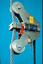
| FUNCTION
The Piab LKV is attached to a stationary line part. The rope is deflected through a slight angle between the two wheels and the clamping jaw. When loaded, the rope tends to straighten. This applies a force to the clamping jaw and so directly to the pull rod. When the set switch value is reached, the pull rod operates a microswitch and a close/open circuit is made. The spring element of the load cell is preloaded, reducing pull rod movement to the last 25% of full load. For the best possible accuracy the LKV is equipped with case-hardened wheels with carefully designed rope grooves. To ensure correct fitting on the rope diameter, the wheels and the clamping jaws are provided with tracks at intervals of 5/32″ (4 mm). The wheels should not be regarded as wheels but rather as moving support points, as the peripheral movement on the wheels at full line load is only about 1/64″ (0.6 mm) (including the extension of the rope). |
||
| PROTECTION AGAINST CORROSION
The Piab LKV is fully pressure tight. Each instrument is tested under pressure. The Piab LKV fully conforms to the international protection specification class IP 67 acc. to IEC 529. Externally it is zinc coated and yellow chromated. The wheel bearings are sealed with 0-rings and lubricated with MoS2. If the LKV is to be used in a very corrosive environment, it may be polyester-lacquered. |
||
| SAFETY
The LKV Overload Guard is not directly included in the rope system and does not affect the construction of the lifting equipment. The locking device prevents unauthorized interference with the switch setting. In spite of the changes that normally take place on the rope diameter, the Piab LKV maintains its set switch value even after fitting to a new rope. As the LKV is fully pressure tight, it is well protected against dust, dirt, damp, frost and other atmospheric conditions. The power-absorbing element consists of specially made Belleville washers dimensioned to resist fatigue. The spring washers cannot be overloaded. The Piab LKV can be overloaded by 100% without affecting the repeatability. |
||
| INSTALLATION
Install the Piab LKV directly to the static line part close to the anchor point or close to a compensating pulley. The line need not be unloaded. Set the switch value with the spanner provided for this purpose. (The LKV can be delivered with the switch value set to trip at the value you require.) Check the switch value with a buzzer or similar device. Connect the LKV electrically, e.g., to the control circuit of the hoisting movement or the top limit switch. Test-load for control and possible readjustment. Seal the set value with the locking clamp and the padlock provided. |
||
| CONTACT FUNCTION
The microswitch has alternative contact functions. When the Piab LKV is used as an overload guard, the normally closed function should always be used. The microswitch has self-cleaning, gold-plated silver contacts, suitable also for operation on low current/voltage (under 10 V and/or 60 mA). The difference between contact at rising and falling load is 5-8%. This hystersis is somewhat reduced at lower loads and increases slightly at higher load values. To avoid “chatter” of the contacts and contactors if the load should start to sway, a time relay can be connected to prolong the reconnection of the hoisting movement. |
||
| ORDERING INFORMATION
The price of an LKV Overload Guard and Slack Line Switch varies according to model. Choose the LKV model that has a switch range that will accommodate the single line part value of the crane or hoist. To obtain the single line part value when used as an Overload Guard, divide the rated capacity of the crane or hoist by the number of line parts. To obtain the single Example: The single line part value of a 10 ton crane with 4 line parts is 2.5 tons or 5000 lbs. The appropriate LKV would then be set at 5000 lbs. when used as an Overload Guard. The appropriate LKV model for a 10 ton crane with 4 line parts is an LKV 4, with a switch range of 880-8,800 lbs. for a single line part to accommodate the single line part value of 5,000 lbs. An LKV 2 is unsuitable since it has a maximum switch value of only 4,400 lbs. versus the required 5,000 lbs. The same LKV 4 can also be used on a crane with 4 parts of line to a maximum of 16 tonne or 35,200 lbs., or a maximum of 24 tonne or 52,800 lbs. with 6 parts of line, etc. |
| Model | Switch Range lbs | Rope Diameter Guide Sizes inch | Unit Wt. lbs | Measurements in inches | ||||||||
|---|---|---|---|---|---|---|---|---|---|---|---|---|
| A Length Pin/Pin | B O/A Length | C O/A Width | D Thickness | |||||||||
| LKV 01
LKV 1 LKV 2 LKV 4 |
90 – 220
220 – 2200 440 – 4400 800 – 8800 |
3/16 – 1/4 – 5/16 (5-8mm)
5/16 – 3/8 – 7/16 (8-12mm) 1/2 – 9/16 – 5/8 (12-16mm) 5/8 – 3/4 (16-20mm) |
11 | 7.78 | 10.5 | 5.59 | 2.36 | |||||
| LKV 08
LKV 8 LKV 12 LKV 16 |
440 – 2425
1760 – 17600 2645 – 26400 |
5/8 – 3/4 (16-20mm)
3/4 – 7/8 (20-24mm) 1 – 1-1/8 (24-28mm) 1-1/8 – 1-1/4 (28-32mm) 1-1/4 – 1-3/8 (32-36mm) |
26.5 | 11.8 | 15.86 | 8.19 | 3.39 | |||||
| LKV 01 | 3525 – 35200 | 1-3/8 – 1-1/2 (36-40mm)
1-1/2 – 1-3/4 (40-44mm) |
48.5 | 18.9 | 23.62 | 8.46 | 5.32 | |||||
The Purchase Price of an LKV includes the following:
| Installation Wrench |
Locking Device | Switch Value Setting |
Wiring Diagram |
|---|---|---|---|
| Adjustment Wrench | 13 Feet of Cable | Certification of Traceability |
Installation Instructions |
Technical Data
| Repeatability | ± 1.5% of the maximum capacity |
|---|---|
| Max Contact Load | 250 V AC, 500 VA, 3 A |
| The Mechanical Life Length of the Microswitch | 20 mill. cycles |
| Working Temperatures | Continuous operation up to +140°F (+60°C). Specially designed LKV’s can be supplied for up to +400°F (+200°C) |
| Cable | 13 Feet (4m) weather and oil resistant cable RDO AWG 15 (4 x 1.5 mm2) |
| Warning Diagram | Also inscribed on the badge plate |